Blog: Cisco

When adding a Cisco switch to an existing switch stack, there is always the chance that the firmware of the new switch will be an older version than the firmware version of the existing switches in the stack. One way to resolve this issue is to enter the command "boot auto-copy-sw" in the existing stack configuration before adding the new switch. The newer firmware version will be copied to the new switch and rebooted to apply the firmware, when it is powered up and connected to the switch stack.

The copy does take some time so it may be prudent to console to the new switch to monitor the status of the copy.


Beginning with ASA OS v9.7, the 5506-X has a new default configuration that allows the ports to be used as switchports, similar to how the 5505 models worked. The default configuration includes a Bridge Virtual Interface (BVI) that has ports G1/2 - G1/7 (6 ports) as members of the BVI. This will apply to models that ship with 9.7 code. However, if you upgrade a device to 9.7, you will have to manually create the BVI group (the upgrade itself does not do this).

Even though the BVI supports up to 6 ports in the BVI, if you try to configure this via ASDM, it only allows you to add 4 ports as members. This actually is a restriction when running the ASA in transparent mode (we rarely do this) instead of routed mode (typical install), but ASDM seems to ignore the mode and apply this restriction regardless. So for an ASA in routed mode, this seems to be an ASDM bug. To work around this, you must add the member ports via the CLI. In addition, the ports cannot have a name defined before you configure the bridge group. However, they must have the naming convention inside1, inside2, etc. to work as part of the BVI group named inside. The default is to assign the members of BVI1 (G1/2 - G1/8) the names inside1 - inside7. The BVI interface is named inside.

Also, the http and ssh commands don't allow you to assign the BVI named interface (inside). Instead, you must add the member name (ex. inside1, inside2, etc.). The snmp-server command actually does allow you to add the BVI interface name, but it doesn't work when you do (seemingly another bug). So again, you'll need to use the member port name instead.


I received several new Cisco 2960x switches to configure and one of them would not boot up stating that the image failed digital signature verification.  These switches have USB interfaces on the front and can be used for file transfer, however more modern USB flashdrives would not work for me.  I had a few older USB flashdrives that worked, so hold on to your flashdrives!

From a working switch, copy the boot image to the USB flashdrive.  
"copy flash:/c2960..../c2960...bin usbflash1:" (or usbflash0: depending on which port it was connected to).

I booted up the switch that wouldn't verify and tried to copy the image onto the switch from usbflash1:  but it told me the copy command was unknown.  Luckily, you can boot off the USB flashdrive image.

I typed "boot usbflash1:/c2960....bin" and it booted the switch where I was able to copy the working image to flash: "copy usbflash1:/c2960....bin flash:/c2960..../c2960....bin"  

​​After overwriting the corrupt image, I rebooted the switch and it passed the verification on the image.


The Cisco-Linksys SRWxxxx series of switches have a simple web interface for management purposes. The interface lacks the ability to see the MAC address table. You can SSH or telnet to the switch, but the menu you get is no better. However there is a hidden CLI (called the lcli, I assume that stands for Linksys CLI) you can access that will allow you additional management capabilities. Once you are logged into an SSH or telnet session and are at the menu, do the following:


Type Ctrl+Z

Hit Enter once

Type in your username and hit Enter


It will not prompt for the password but it will give you a <hostname># prompt. From here, you can type ? see the available commands. To see the MAC-address table, type show bridge address-table.


A customer had several Cisco 2960 switches that were not managed and did not want us to come onsite to configure them for management. Since she had a Cisco console cable and the switches currently did not have a password, we were able to assist her remotely. The switches were already cabled together and in production. There was an intentional loop cabled between the switches for redundancy. This loop was being shut down by spanning-tree.

As I started entering the global configuration commands on the first switch, I lost my connection to their network because I was connected over the Internet. The commands I had just entered was “spanning-tree portfast bpduguard default”, which enables BPDU Guard globally. Since the switches were already cabled, when I enabled BPDU Guard globally, it put the interfaces connected to the other switches in an err-disabled state as it should. I walked the customer through removing the global spanning-tree commands and performing a shut/no shut on the interfaces connected to the other switches. This allowed my remote connection to come back online.

The proper order to perform these changes is to add the “spanning-tree portfast disable” command on all interfaces connected to other switches before enabling the global spanning-tree options. After the individual interfaces were configured, I entered “spanning-tree portfast bpduguard default” globally with no issues. 


CoNetrix Website | Contact Information

Cisco Hardware Issue with Clock Signal Component


On February 2, Cisco released information about an issue affecting many of their hardware systems. This issue may cause eventual hardware failure on specific models and hardware versions after 18 months or longer.

The most common affected systems include ASA 5506, 5508, 5516 firewalls, and 4321, 4331, and 4351 routers.

Details about the issue with a complete list of affected hardware is available at http://www.cisco.com/c/en/us/support/web/clock-signal.html. The "Field Notices" tab contains links to the specific hardware.

For CoNetrix Technology customers, we are currently reviewing all documentation to determine those customers with affected hardware. We will contact those customers when additional action is needed.

Other CoNetrix customers should review their installed Cisco hardware or contact their IT service provider as soon as possible.

CoNetrix Technology customers can contact Support at 806-687-8600 or support@conetrix.com with any questions or concerns.


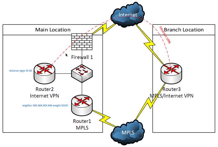
One of our customers is using an MPLS network for their WAN connections. but they have installed backup Internet connections at their branch locations in order to maintain connectivity to the corporate office if one of the MPLS connections was to fail. See the diagram below for reference:

In order to configure the backup VPN, a VPN tunnel must be built between the main location and the branch location, in this case Router2 and Router3, respectively. Also, GRE tunnels were built between these routers so that routes could be dynamically exchanged using EIGRP, which also requires adding static routes for the GRE tunnel interfaces to route this traffic out the Internet connections instead of over the MPLS connection. All routers participate in the same EIGRP process. BGP and EIGRP are redistributed into each other on Router1. The EIGRP routes will not be preferred on the branch router (Router3) because EIGRP has a higher administrative distance (90) than BGP (20) and the BGP routes will be used. On the Internet VPN router (Router2), these routes will be preferred because EIGRP internal has a lower administrative distance (90) than external EIGRP (170). This behavior can be changed by adding the  “distance eigrp DesiredInternalAdminstrativeDistance DesiredExternalAdminitrativeDistance” (“distance eigrp 90 80” in this case) command to the EIGRP configuration.

This setup will work for failover, but will additional configuration is needed for the router to automatically failback to the MPLS connection. If the failure is at Router3, Router3 will return to using BGP routes from MPLS when the connection is restored. By default, Router1 will continue to use the routes obtained via EIGRP because the weight of these injected routes of 32768 is greater than the default weight of 0 for learned routes. This can be resolved by setting the learned routes from the BGP neighbor (ISP) to a higher weight than the injected routes. In this case, “neighbor NeighborIPAddress weight 35000” was added to the BGP configuration on Router1. These higher weight routes overwrite the injected routes. 

 The combination of changing the administrative distance in EIGRP and BGP neighbor weights allows this connection to fail to the Internet VPN and return to the MPLS connection dynamically.


While rebooting a Cisco 2960 switch to back out some configuration changes, I was not able to route traffic through the switch. After some troubleshooting, I noticed the following the error (with "terminal monitor" enabled):
 
%ILET-1-AUTHENTICATION_FAIL: This Switch may not have been manufactured by Cisco or with Cisco's authorization.  This product may contain software that was copied in violation of Cisco's license terms.  If your use of this product is the cause of a support issue, Cisco may deny operation of the product, support under your warranty or under a Cisco technical support program such as Smartnet.  Please contact Cisco's Technical Assistance Center for more information.
 
A quick search revealed this to be an IOS bug (actually 3 related issues). The switch shipped with 15.0(2)EX5 code. The immediate work-around was to power-cycle the switch instead of doing a soft boot (reload). The root cause of the issue is related to the "internal i2c bus" getting into a bad state. Once it does, the bus maintains power through a soft boot, so a reload does not resolve the issue. A power-cycle is required.
 
An upgrade to 15.2(2)E3 (MD) or 15.2(4)E (ED) or later will resolve this issue. http://www.cisco.com/c/en/us/support/docs/switches/catalyst-2960-x-series-switches/118837-technote-catalyst-00.html


Cisco IOS XE devices boot into a Linux kernel first, then load IOS as a module. If you just power off the device (as we are used to doing with IOS devices), you will see disk-errors (assuming you are connected and monitoring the console) when you power it up that get auto-corrected (hopefully). This happens because log files related to the Linux kernel are still in use when you power off the device.
 
To avoid this, the documentation states to issue a reload before powering down to ensure all the log files are closed correctly, but it isn't clear at what point you can then power off. Of course if you dont, it come-back up as a result of the reload command.
 
I found a link online that recommends issuing the 'reload pause' command instead. When the device gets to the pause, it will show you a 'Enter [continue]…' prompt. At this point, you can safely power off the device and it will not have any disk errors when it boots up again.
 
This assumes you are connected to the console. Not a bad assumption as it is a bit hard to physically power down a router or switch remotely. But if you are not on the console (maybe you have a customer that will to pull the plug for you), you can still issue the reload pause command and wait about 60 seconds. That should be enough time for the device to get to that pause.


Recently we've been experiencing a problem with the Cisco AnyConnect client disconnecting and reconnecting shortly after the initial connection is established. Originally we thought that this was a bug in the client. Cisco recommended switching to an IKEv2 connection profile, but the disconnect problem was never resolved, even with updated versions of the client. During a recent remote session with Cisco support, the root cause of the disconnects was discovered.

In later versions of the AnyConnect client, there are two protocols in use:  SSL and DTLS. DTLS is a variant of TLS that uses datagrams which are sensitive to delay. After authentication, the client attempts to negotiate a DLTS connection. If that negotiation is unsuccessful, the client disconnects and reconnects using SSL only. DTLS uses UDP port 443. In our test environment, the remote access firewall is behind another firewall that was only allowing TCP port 443 through. After updating the firewall rule to allow UDP port 443 as well, the disconnects stopped occurring.